

C83600 bronze casting, also called CDA 836 casting, is a practical choice for machined copper-alloy components that need a balance of castability, corrosion resistance and manufacturing economy. Buyers encounter this material in valve bodies, pump components, industrial fittings, bushings and selected electrical hardware. Its familiar nominal composition is 85% copper, with approximately 5% each of tin, lead and zinc.
However, selecting an alloy name is only the beginning. Reliable performance depends on the casting process, section geometry, melt control, machining requirements and inspection plan. This technical guide explains how engineers and purchasing teams can specify C83600 castings clearly, compare manufacturing routes and avoid common mistakes when ordering finished components.
What is C83600 bronze casting?
UNS C83600 identifies a cast copper-tin-lead-zinc alloy. CDA 836 is the widely used shortened commercial designation. Suppliers may describe the same material as ounce metal, 85-5-5-5 bronze, leaded gunmetal or leaded red brass. The Copper Development Association formally groups C83600 within cast red and leaded red brasses. Consequently, the commercial word bronze should always be accompanied by the UNS number on a drawing or purchase order.
This distinction matters because bronze is a broad trade term. A quotation for unspecified bronze might describe a tin bronze, aluminum bronze or another copper alloy with very different machining behavior and mechanical performance. Naming C83600 removes much of that ambiguity, but the product standard and manufacturing route still need agreement.
A C83600 casting is produced by melting a controlled charge and solidifying the metal in a mold. Subsequent operations can include removing gates and risers, cleaning, dimensional inspection and CNC machining. The finished component may therefore combine economical cast external geometry with accurately machined bores, threads, sealing faces and mounting surfaces.
C83600 chemical composition and metallurgy
The following principal-element ranges are reported by the Copper Development Association C83600 alloy database. They are percentages by mass. The nominal 85-5-5-5 description is convenient shorthand; it does not replace the permitted ranges and residual-element restrictions in the applicable specification.
| Element | Range by mass | Engineering relevance |
|---|---|---|
| Copper | 84.0–86.0% | Forms the principal metallic matrix |
| Tin | 4.0–6.0% | Influences strength and corrosion behavior |
| Lead | 4.0–6.0% | Supports machinability; restricts some applications |
| Zinc | 4.0–6.0% | Contributes to alloy and foundry behavior |
Minor elements also matter. A heat can satisfy the four headline ranges and still fail the ordered specification because an impurity exceeds its limit. The inspection certificate should therefore report the elements required by the governing standard, rather than simply state “85-5-5-5 confirmed.” Copper calculation rules and process-specific chemistry notes also deserve attention.
Why composition does not tell the whole story
As the metal freezes, local cooling conditions influence the distribution of phases and the resulting structure. Thick bosses and thin webs do not necessarily solidify at the same rate. Feeding, segregation and cooling history can therefore affect local properties even when the overall heat analysis is correct.
Lead does not act like a uniformly dissolved strengthening addition. Its distribution within the casting contributes to machining behavior, while also making application restrictions and responsible handling relevant. Specifying the right chemistry cannot compensate for shrinkage cavities, inclusions or poorly controlled machining.
Foundries should segregate charge materials by alloy family, maintain traceability for returns and verify the melt using a suitable analytical method. Unknown mixed scrap introduces avoidable uncertainty. Recycled feedstock can be entirely appropriate when chemistry, cleanliness and process controls are maintained; recycled content alone neither proves nor disproves quality.
Mechanical properties: distinguish casting route and test basis
Published C83600 strength values must be read alongside the product form. The CDA database lists sand-cast minimum tensile strength of 30 ksi, yield strength of 14 ksi at 0.5% extension and elongation of 20%. These correspond approximately to 207 MPa and 97 MPa. Typical values can exceed minimum requirements, but typical results are not guaranteed acceptance criteria.
For comparison, Wieland Concast’s C83600 continuous-cast datasheet, referencing ASTM B505/B505M-23, lists minimum tensile strength of 248 MPa, minimum yield strength of 131 MPa and minimum elongation of 15%. These continuous-cast figures should not be copied into a sand-casting drawing without technical review.
Test-bar location, specimen preparation and the governing specification affect how results should be interpreted. A separately cast coupon does not reproduce every thermal condition inside a complex component. Where local performance is critical, agree on representative testing and acceptance requirements before placing the order.
Strength values are not allowable design stresses
An engineer must consider loading direction, stress concentrations, fatigue, temperature and the consequence of failure. Minimum tensile strength is not a direct working-stress recommendation. A threaded boss subjected to tightening loads may require a different assessment from a housing supporting a steady distributed load.
Likewise, pressure capability belongs to the finished design and its qualification. There is no universal pressure rating for every CDA 836 casting. Wall thickness, porosity acceptance, joint design, temperature, fluid compatibility and the relevant equipment standard all influence safe service.
Choosing the C83600 casting process
Sand casting for custom shapes
Sand casting is a flexible route for irregular bodies, cored passages and geometries that would waste substantial material if machined from solid stock. Pattern and core design determine the basic shape, while machining establishes the critical interfaces. It is often worth reviewing the component with the foundry before the drawing becomes fixed.
The design review should identify parting lines, draft, core supports, feeding locations and machining datums. Deep pockets and narrow internal passages can make cleaning and inspection difficult. A small geometry change may improve mold filling or allow a more stable core without changing the component’s function.
Shell molding where repeatability justifies tooling
Shell molding may be considered when the geometry, production quantity and foundry capability support the investment. Tooling cost, achievable surface condition and dimensional repeatability should be assessed together. It is better to request a process-specific capability proposal than assume that the process name guarantees a particular tolerance.
For either sand or shell molding, the supplier should distinguish as-cast dimensions from machined dimensions. A close bearing bore and a nonfunctional external rib do not need identical tolerance requirements. Separating them helps direct inspection effort toward features that affect assembly and operation.
Continuous and centrifugal casting
Continuous-cast bar or tube can be economical for components dominated by rotational machining. Centrifugal casting may suit appropriate rings and hollow forms. These routes produce different starting shapes and solidification conditions from individually molded near-net components. They should be compared using the finished-part cost and applicable material requirements.
A simple sleeve might be efficiently machined from tube, whereas an asymmetric body with multiple branches may favor a shaped casting. Compare material utilization, machining time, tooling amortization and inspection requirements. The cheapest kilogram of raw material does not necessarily produce the lowest-cost accepted component.
Foundry controls that prevent casting defects
Sound castings depend on an organized sequence: charge verification, melting, chemistry adjustment, mold preparation, pouring, solidification and cleaning. Inspection is essential, but it cannot create soundness after an unstable process. Production records should connect the finished batch to its heat and relevant manufacturing controls.
Shrinkage and feeding
When isolated heavy sections remain liquid after adjoining regions freeze, they can become difficult to feed. Appropriate risers, transitions and, where suitable, chills help manage solidification. Abrupt intersections deserve particular attention because they can create local hot spots that are not obvious from the external outline alone.
A machining allowance should not be used to conceal an unresolved feeding problem. Removing the outer layer may expose subsurface cavities close to a sealing face or thread root. Trial production should examine the actual machined regions, since an acceptable external casting can still reveal defects during finishing.
Gas, inclusions and surface discontinuities
Melt cleanliness, mold condition and pouring practice influence defect risk. Excessive turbulence can introduce unwanted films or inclusions. Inadequate venting and inappropriate moisture conditions may contribute to gas-related defects. Corrective action should follow the identified mechanism rather than rely on repeatedly increasing pouring temperature.
Defect descriptions should be specific. “Porosity” can refer to different mechanisms requiring different remedies. Photographs, sectioned samples, radiographic observations and process records can help distinguish rounded gas cavities from irregular shrinkage or embedded nonmetallic material. This makes supplier improvement discussions more productive.
CNC machining of CDA 836 castings
C83600 is selected partly for its useful machinability. Nevertheless, a stable machining process depends on workholding, tool geometry, cutting conditions and the quality of the starting casting. Interrupted cuts through cast surfaces, thin walls and asymmetric fixtures require particular care.
Establish reliable datums early. If an external cast surface varies, using it as the sole reference for several critical bores may create inconsistent wall thickness or misalignment. The machining sequence should connect the drawing’s functional datum structure to practical locating surfaces and inspection methods.
Threads, sealing faces and burr control
Thread callouts should identify the thread system, size, pitch, class and required engagement. Tapered pipe threads and parallel fastening threads are not interchangeable. A go/no-go gauge can verify an important aspect of conformity, but it does not replace checking depth, alignment or the associated sealing geometry.
For gasket faces or sliding interfaces, specify surface texture and any relevant flatness requirements. Avoid applying one unnecessarily fine finish to every surface. Burr removal deserves its own work instruction, especially around cross-drilled holes, internal passages and small threaded features where loose material can remain trapped.
Cleaning should match the end use. A hydraulic or fluid-handling component may need controlled removal of chips and residual media from internal passages. Packaging must then preserve that cleanliness. Inspection should occur after the relevant finishing operations, since blasting, polishing or handling can alter edges and surfaces.
Designing tolerances and machining allowances
A useful casting drawing clearly separates raw casting requirements from finished machining requirements. State the chosen general casting tolerance framework, identify controlled dimensions and add geometric tolerances where they protect function. Blanket application of very tight tolerances increases cost without necessarily improving the assembly.
Machining allowance depends on component size, mold process, distortion risk and datum strategy. There is no single allowance suitable for every C83600 part. Allow enough stock to clean up the intended surfaces, but recognize that excessive stock increases machining time and can complicate feeding around heavy sections.
Uniform wall transitions, sensible fillets and accessible tooling paths improve manufacturability. Where a large boss meets a thin wall, review both stress concentration and solidification. The best solution often balances structural performance with mold filling and feeding rather than optimizing either consideration in isolation.
Where C83600 bronze castings are used
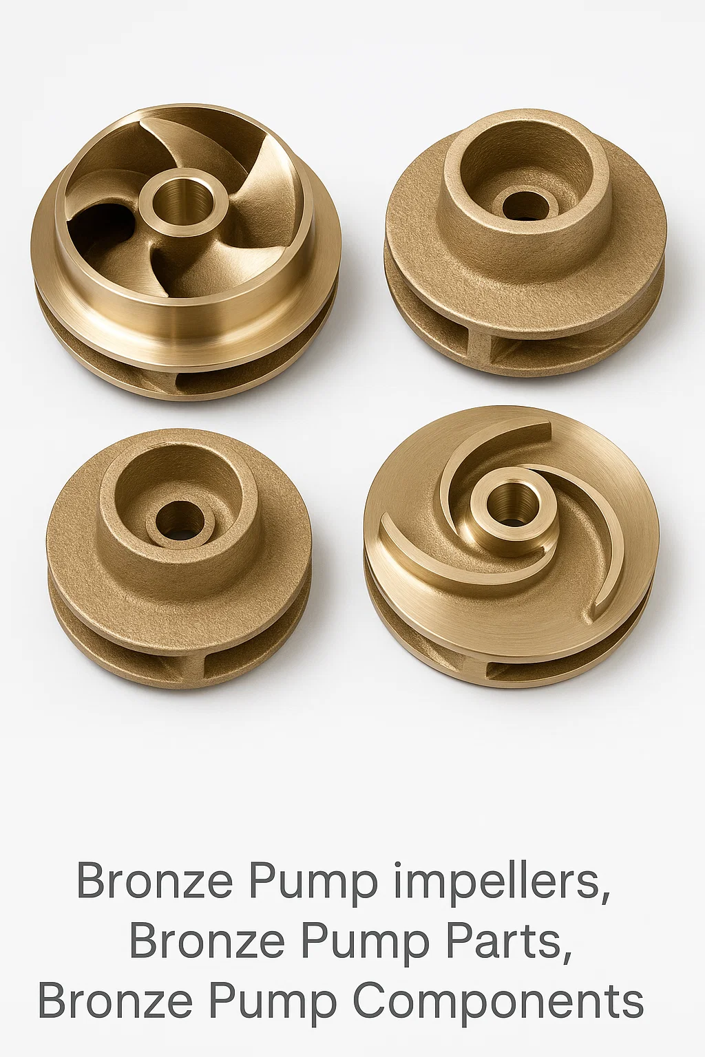
Valve bodies, pump parts and industrial fittings
Fluid-handling components are a familiar application area, provided the alloy is compatible with the actual medium and service conditions. Buyers should describe temperature, pressure, fluid composition and expected duty. A material that performs acceptably in one water system should not automatically be approved for another chemical environment.
For pressure-containing parts, agree on the test method, test pressure, hold time and permissible leakage. Hydrostatic and pneumatic tests involve different procedures and risks. The test plan should follow the applicable equipment requirements and use a controlled, documented setup appropriate to the component.
Bushings and moderately loaded wear components
CDA 836 may be considered for certain bushings, small mechanical parts and sliding components. Selection requires evaluation of bearing pressure, sliding speed, lubrication, temperature and counterface condition. A familiar bronze designation alone does not establish suitability for heavily loaded or poorly lubricated duty.
Where wear dominates the design, compare purpose-selected bearing alloys and evaluate the complete operating system. Shaft finish, alignment and lubricant supply can matter as much as nominal alloy strength. Service failures should therefore be investigated at the assembly level rather than attributed immediately to composition.
Electrical and transformer hardware
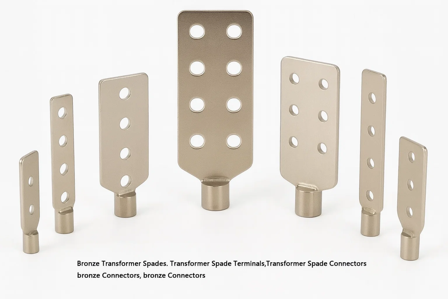
Selected electrical hardware can use cast bronze to obtain a practical combination of geometry, mechanical integrity and environmental durability. The site’s transformer spade terminals and copper bronze bolted lugs illustrate related component families that require application-specific material selection.
Do not treat C83600 as electrically equivalent to high-conductivity copper. Current capacity depends on cross-section, joint resistance, contact pressure, temperature rise and installation conditions. A connector requires qualification as an assembly; an alloy certificate does not demonstrate compliance with an electrical connector performance standard.
Bolted interfaces also need control of fasteners, tightening procedures and contact surfaces. If plating is specified, define its purpose, thickness and acceptance requirements. Coatings can support an engineered interface, but they cannot remedy inadequate contact geometry or an unsuitable underlying material choice.
Corrosion resistance and service limitations
Corrosion resistance is always relative to the environment. Evaluate dissolved species, pH, flow conditions, operating temperature and contact with dissimilar metals. Stagnant crevices can behave differently from exposed surfaces, and deposits may alter local conditions. A general statement that bronze resists corrosion is insufficient for a demanding specification.
For marine or chemically aggressive service, compare alternative alloys against documented operating conditions. The presence of copper and tin does not make every bronze equally resistant to erosion, cavitation or localized attack. Service history, testing and a corrosion specialist’s review may be appropriate where failure consequences are substantial.
C83600 contains intentional lead and should not be described as lead-free. Potable-water, food-contact and restricted-substance applications require review of the applicable product and market requirements. Choose a compliant material and obtain relevant evidence rather than assume that a protective coating automatically resolves material restrictions.
C83600 versus LG2, C93200 and aluminum bronze
LG2 is often mentioned alongside C83600 because these commercial alloy families share a nominal copper-tin-lead-zinc concept. However, historical British specifications, modern European designations and UNS requirements should not be treated as automatically identical. Check composition limits, product form, mechanical requirements and the exact standard edition before approving substitution.
C93200 is a different UNS alloy commonly considered for bearing applications. It is not a universal replacement for C83600. Likewise, aluminum bronzes belong to a different alloy family and may be chosen for different combinations of strength, corrosion behavior and wear performance. A substitution should follow engineering review.
For related casting options, review LG2 bronze casting and C95500 aluminum bronze casting. Compare them against the intended operating duty rather than rank them as universally better or worse. Material choice is a design decision tied to function.
Inspection and quality documentation
An effective inspection plan connects each risk to a verification method. Chemistry addresses alloy identity; dimensional inspection addresses geometry; mechanical testing addresses specified material properties. None of these alone demonstrates leak tightness, internal soundness or electrical performance. Select complementary checks based on the component’s function.
- Heat analysis and traceability to the supplied batch.
- First-article dimensional results against the approved drawing revision.
- Thread and functional gauging for assembly-critical features.
- Mechanical testing where required by the ordered specification.
- Surface or volumetric examination where technically appropriate.
- Pressure, leakage or assembly testing when specified.
Liquid penetrant inspection can reveal suitable surface-breaking discontinuities but does not establish internal soundness. Radiography has different strengths and limitations, including geometry and interpretation requirements. State the examination extent and acceptance criteria in advance; “NDT required” is too vague for consistent quotation or acceptance.
Agree on any restrictions governing impregnation, weld repair or other recovery methods. Such operations can affect customer approval, traceability and service suitability. A supplier should disclose proposed repairs and follow the applicable standard and purchase requirements rather than assume that passing a final leak test makes every repair acceptable.
How to specify and purchase CDA 836 casting
The ASTM copper standards catalog distinguishes standards for sand, centrifugal and continuous castings. ASTM B584 addresses copper-alloy sand castings for general applications; ASTM B505/B505M addresses continuous castings. Identify the appropriate product specification, confirm that its scope and alloy coverage suit the part, and name the agreed edition.
A complete request for quotation should include a controlled drawing, three-dimensional model where available, annual demand and order quantity. State whether the supplier is quoting a raw casting, a rough-machined blank or a finished component. Include inspection, marking, packaging and documentation expectations so competing quotations cover the same deliverable.
For example, request “UNS C83600 sand casting to the agreed applicable specification and edition, machined to drawing revision C, with heat traceability, specified chemistry certification and first-article inspection.” Add the actual pressure-test procedure, surface requirements and acceptance criteria where relevant. The example is a purchasing structure, not a substitute for engineering approval.
Evaluate total cost and production readiness
Review tooling ownership, pattern life, replacement arrangements, sampling cost and lead time separately from the piece price. Confirm how drawing changes affect tooling and inventory. For repeat orders, agree on revision control and notification requirements when the supplier changes a significant process, source or subcontract operation.
A pilot batch should demonstrate repeatability across the required features and operations. Examine machining cleanup, thread consistency, sealing-face quality and documentation completeness. Resolve recurring defects before scaling production. Approval based only on one attractive sample can conceal variation that becomes expensive during routine assembly.
Frequently asked questions about C83600 bronze casting
Are C83600 and CDA 836 the same alloy?
CDA 836 is the common shortened designation associated with UNS C83600. For procurement, use the full UNS number together with the product specification, manufacturing route and drawing requirements. This helps avoid confusion with generic bronze descriptions or unrelated commercial grade names.
Is C83600 bronze or brass?
It is commercially called bronze or gunmetal, while the CDA classification places it among leaded red brasses. Both terms appear in industry. The UNS designation is therefore more useful than the family name when identifying the exact material for a casting order.
Can a C83600 casting be supplied fully machined?
Yes, a procurement package can cover casting and subsequent machining. Define finished dimensions, threads, geometric tolerances, surface texture and inspection requirements. Confirm the supplier’s actual process capability and documentation scope rather than assuming that all cast surfaces will meet machined-part tolerances.
Is C83600 suitable for every transformer connector?
No. Suitability depends on electrical duty, mechanical loads, contact design and qualification requirements. Engineers should evaluate temperature rise, resistance and joint stability for the complete connector. High-conductivity copper and different bronze alloys can serve different purposes within electrical equipment.
Can continuous-cast properties be used for sand castings?
They should not be transferred automatically. Published values depend on product form and specification. Use requirements applicable to the ordered manufacturing route and agree on the test basis. Typical handbook values should remain clearly distinguished from contractual minimum properties.
Discuss your C83600 casting requirement
For a technical quotation, share your drawing, required quantity, application and inspection needs with sales@brass-parts-india.com. Identify C83600 or CDA 836 explicitly and state whether you require an as-cast or fully machined component. A clear specification allows the manufacturing route, tooling proposal and quality plan to be evaluated together.
Explore the site’s brass and copper casting components for related manufacturing requirements. The most useful starting point is the component’s actual duty: what it carries, how it connects and how it will be inspected. That information turns an alloy inquiry into a practical, reviewable manufacturing requirement.
Technical references: Copper Development Association C83600 alloy database; Wieland Concast C83600 continuous-cast datasheet; ASTM copper standards catalog, linked above. Published properties are reference information; the agreed product specification and approved drawing govern supply.