-
-
Plot 10, GIDC Industrial Estate, Udyog Nagar, Jamnagar. India.

Plot 10, GIDC Industrial Estate, Udyog Nagar, Jamnagar. India.
Free-cutting brass CNC machined parts are produced from machining brass selected for chip control and repeatable turning operations. Typical components combine threads, shoulders, bores, flats and grooves in a compact geometry for OEM mechanical and electrical assemblies. Cable Glands India supplies drawing-based free-cutting brass components for electrical OEMs, EPC contractors, power utilities and industrial distributors. Typical parts include threaded inserts, hexagonal adapters, knurled knobs, stepped bushes, connector shells, precision spacers. Specify the material grade, dimensions, finish and inspection requirements when requesting a quotation.
Price: US$ 14.50/kg | Standard tolerance: ±0.05 mm
The final quotation confirms drawing complexity, quantity, chargeable weight, finishing, documentation and delivery terms.
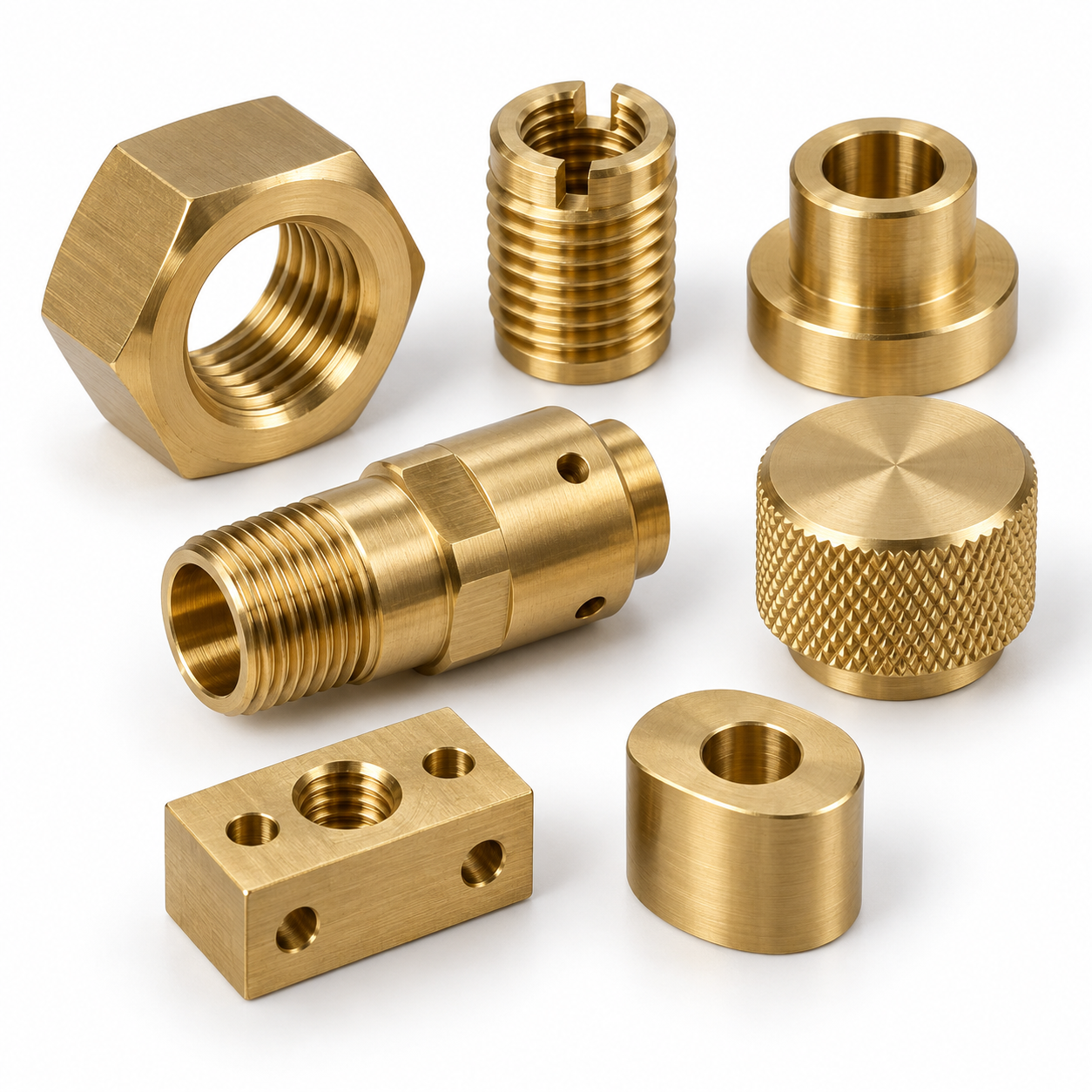
Free-cutting brass CNC machined parts are produced from machining brass selected for chip control and repeatable turning operations. Typical components combine threads, shoulders, bores, flats and grooves in a compact geometry for OEM mechanical and electrical assemblies. Typical enquiries include threaded inserts, hexagonal adapters, knurled knobs and related drawing-based components. The part specification should connect each feature to its function: location, fastening, conduction, spacing or fluid passage. A model communicates shape, while the controlled drawing defines acceptance. Identify mating parts and assembly direction so shoulders, reliefs and access clearances can be reviewed before a quotation is finalized. This is especially useful when one component combines several operations or must fit an existing assembly without adjustment.
The selected free-cutting brass grade affects machining response and the finished component’s suitability. Compare chemical composition, mechanical condition, corrosion exposure and any electrical or thermal requirement before approving stock. C36000 and CW614N are leaded brasses. They must not be described as lead-free or assumed suitable for potable-water service without the required material and finished-product assessment. Similar trade names are not proof of exact international equivalence. A commercial alloy name alone is not a complete purchase specification. State the governing material standard and revision, stock form and required certificate. If a substitute is considered, record the engineering approval rather than relying only on a distributor cross-reference or a similar appearance.
The standard tolerance for these parts is ±0.05 mm. Define the reference face, axis or datum system used to inspect the component. Position, perpendicularity, coaxial features and surface texture need their own drawing requirements when they influence assembly. A nominal dimension without its tolerance can lead to different interpretations during machining and inspection. Provide limits for critical interfaces, and distinguish functional dimensions from reference information. For hexagonal adapters, identify the features that control location rather than applying unnecessarily restrictive requirements everywhere.
The machinability of free-cutting brass supports efficient chip formation, but it does not remove the need to control tool wear, thin-wall distortion, thread fit or burr formation. Tool access, chip evacuation and the order of roughing and finishing influence the practical process route. Thin sections, interrupted cuts and intersecting holes deserve particular attention during drawing review. The manufacturing plan should establish how the component is held without damaging finished surfaces. Where stepped bushes require a second operation, identify the datum transferred between setups. Agreement on these details supports consistent inspection and avoids assuming that machine type alone determines the final result.
Available finish routes are specified as natural brass, nickel plating, tin plating or other specified finishes. The drawing should define whether a surface is functional, cosmetic or both. Break sharp edges in accordance with the agreed requirement while protecting contact faces, thread starts and sealing lands. Cleaning needs depend on the service: residual chips, machining fluid or polishing compound can affect assembly. For connector shells, identify surfaces that must remain free from coating or mechanical damage. Confirm whether dimensional acceptance is required before finishing, after finishing or at both stages.
Procurement teams should describe precision spacers by a controlled part number rather than by a photograph alone. A complete enquiry includes the drawing revision, quantity, material designation, finish and destination. State whether the order is a prototype, scheduled release or repeat requirement. The listed kilogram rate provides a commercial reference, but the written quotation must define its scope and weight basis. Keeping technical and commercial information together helps electrical OEMs, EPC contractors, utilities and distributors compare offers on the same requirements.
For free-cutting brass components, specify through holes and blind holes separately, including usable depth and any drill-point allowance. Identify cross holes that intersect a bore so the deburring approach can be considered. A dimensioned bore may serve as clearance, location, bearing support or a flow passage; these functions can require different finish and inspection methods. Provide the mating diameter or fit requirement where relevant. Do not infer a sealing or pressure capability from an internal passage alone.
Define thread system, nominal size, pitch, internal or external form, engagement length and acceptance class. Metric, unified and pipe threads are different specifications and should not be mixed under a generic threaded-parts description. Include the required gauge basis and any post-plating allowance. For knurled knobs, check wall thickness around the thread and provide adequate entry chamfers. Torque, locking method and service loading belong to the assembly specification and should be supplied when they affect the component design.
Grooves and slots should show width, depth, root radius and position from an identified datum. A sharp internal corner shown in a model may require an alternative radius or a different operation. State whether a groove locates a retaining element, provides clearance or carries a seal. The required edge condition should preserve the intended function. With CNC turning and secondary milling, access and component support influence the sequence; review narrow features and deep recesses before fixing the final drawing.
Describe the actual function of each mating face. Mechanical seating, electrical contact and sealing do not necessarily require the same preparation. Specify flatness or roughness where the assembly needs it instead of treating the general ±0.05 mm dimensional tolerance as a surface specification. For threaded inserts, identify contact zones, prohibited coating areas and acceptable handling marks. The equipment designer remains responsible for validating the complete joint under operating loads, temperature and environmental conditions.
Inspection should follow the drawing’s critical features and the agreed sampling plan. Suitable measurement methods depend on feature size, accessibility and tolerance; the presence of a CNC machine is not an inspection record. Specify whether a first-article report, dimensional layout, material certificate or batch identification is needed. Maintain a clear connection between the drawing revision and ordered free-cutting brass grade. Special documentation and retained samples should be requested before production so the commercial offer includes the required work.
Protect finished threads, bores and contact faces during handling and transport. Separate components where metal-to-metal movement could damage a functional surface. Specify part-number labels, batch information and package quantities when they are needed for stores control or assembly lines. Repeat orders should refer to the approved drawing revision and any accepted deviations. If precision spacers are supplied with other components, identify each item independently to avoid mixing similar-looking materials or variants during receipt and installation.
| Parameter | Specification / ordering information |
|---|---|
| Product | Free Cutting Brass CNC machined Parts |
| Brand | Cable Glands India |
| Manufacturing route | CNC turning and secondary milling |
| Standard dimensional tolerance | ±0.05 mm |
| Raw material | free-cutting brass; specify grade, product form and condition |
| Dimensions and geometry | Customer drawing; confirm feasibility before order |
| Thread specification | Drawing-defined system, size, pitch, class and engagement |
| Surface treatment | natural brass, nickel plating, tin plating or other specified finishes |
| Surface roughness and geometric controls | Individually specified where required; not implied by general tolerance |
| Inspection and documents | Agreed inspection plan, material records and reporting scope |
| Listed rate | US$ 14.50/kg; written quotation defines scope |
| Order information | Part number, revision, quantity, finish, documentation and destination |
The following table supports material discussion. Cross-references are not unconditional equivalents: chemistry limits, product standard, temper or condition and testing requirements may differ. The purchase order should name the exact approved specification. Confirm current standard requirements and obtain material documentation for the selected stock.
| Grade / designation | International reference or description | Engineering qualification |
|---|---|---|
| C36000 | UNS free-cutting brass | Leaded machining grade; chemical limits and condition follow the ordered specification |
| CW614N | CuZn39Pb3; legacy CZ121 reference | European leaded machining brass; compare limits before substitution |
| CW617N | CuZn40Pb2 | Distinct forging-oriented brass that may be machined; not identical to CW614N |
| C69300 / CW724R | Silicon-containing lead-free brass family | Alternative when required; cutting behaviour differs |
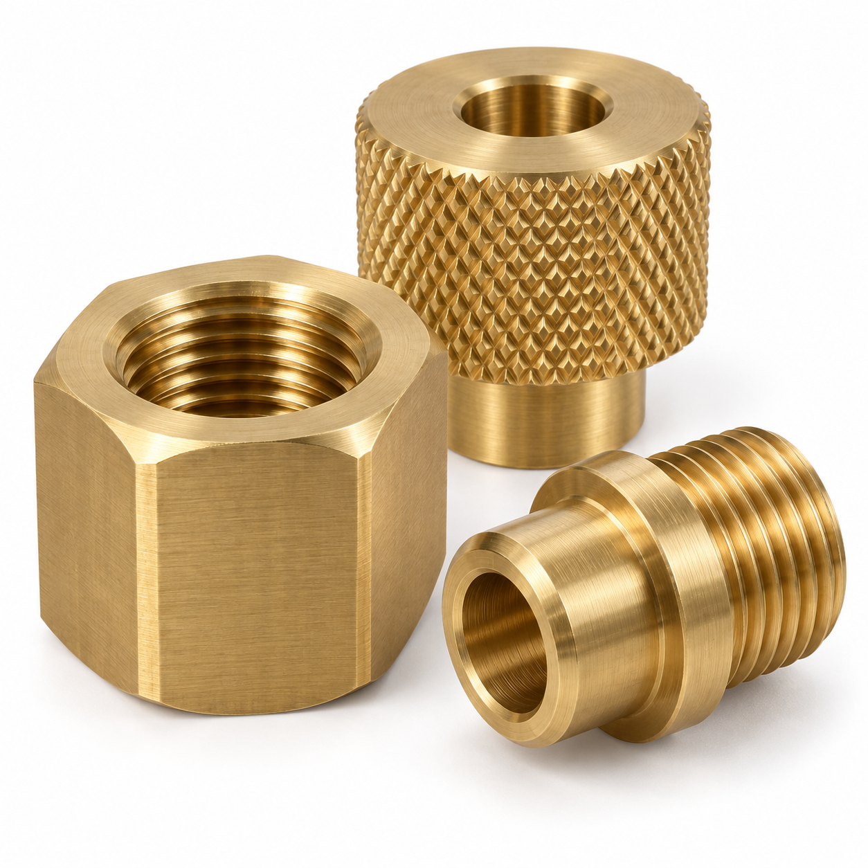
| Variant | Features to define |
|---|---|
| threaded inserts | Overall length, steps and functional datums |
| hexagonal adapters | Mating diameters, shoulders and surface condition |
| knurled knobs | Thread details, engagement and entry geometry |
| stepped bushes | Bore limits, wall thickness and edge breaks |
| connector shells | Ports, flats, mounting holes and contact zones |
| precision spacers | Thickness, location and handling requirements |
| Customer / sector | Potential component role | Information needed |
|---|---|---|
| Electrical OEMs | Connector, terminal, enclosure or mounting interfaces | Electrical function, mating geometry, finish and assembly validation |
| EPC contractors | Project-specific equipment and installation components | Approved drawings, schedules and project documentation |
| Power utilities | Equipment maintenance and replacement components | Original specification, operating conditions and approval route |
| Distributors | Repeat supply of identified drawing-based parts | Part numbers, revisions, quantities and packaging |
| Instrumentation and industrial equipment | Spacers, housings, adapters and mechanical interfaces | Loads, environmental exposure and functional tolerances |
Application suitability depends on the complete design. C36000 and CW614N are leaded brasses. They must not be described as lead-free or assumed suitable for potable-water service without the required material and finished-product assessment. Similar trade names are not proof of exact international equivalence. Provide temperature range, exposure conditions and expected mechanical or electrical function when these affect material choice. Equipment ratings, pressure limits and compliance claims require assembly-level evidence. The component drawing should capture the features needed to support that validation rather than relying on a generic catalogue description.
Review the free-cutting brass grade, dimensions, datum structure and finish together. Identify features that need additional clarification, such as inaccessible burrs, incomplete thread callouts or conflicting limits. Confirm the controlled revision and obtain approval for any proposed change before manufacture.
Select the specified stock form and condition, then plan cutting allowances and workholding. The machinability of free-cutting brass supports efficient chip formation, but it does not remove the need to control tool wear, thin-wall distortion, thread fit or burr formation. The setup should provide access to required features while protecting surfaces that are already finished.
CNC turning and secondary milling creates the principal geometry. Roughing removes excess material before the relevant finishing operations establish drawing features. Drilling, boring, tapping, slotting or secondary milling are added where required. Tool selection and cutting conditions depend on the actual alloy and geometry.
Remove burrs to the agreed edge specification, especially at intersecting holes and thread starts. Avoid rounding a functional edge beyond the drawing allowance. Clean the components using a method compatible with the material and subsequent finishing or assembly requirements.
Apply natural brass, nickel plating, tin plating or other specified finishes only as ordered. Check the effect on fit and functional surfaces, including masked areas. Verify the required dimensions in the agreed finished condition and review the specified inspection records before release.
Identify parts and packages against the order and drawing revision. Protect functional surfaces for the selected transport route. Include the agreed documentation and distinguish separate batches or materials where the purchase order requires traceability.
Quality requirements must be tied to the supplied part and order. Ask for the current applicable ISO 9001 certificate if supplier quality-system certification is required; confirm its scope and validity. This page does not assert unverified certification. Material records, including an EN 10204 document where specified and available, should match the supplied grade and batch. A material certificate does not replace dimensional inspection or finished-equipment approval.
| Requirement | How to specify it |
|---|---|
| Material conformity | Exact grade, standard, condition and certificate type |
| Dimensional acceptance | Drawing revision, critical features and inspection plan |
| Restricted substances | Applicable jurisdiction, permitted limits and evidence required |
| Finish verification | Coating type, thickness, masking and acceptance method |
| Application approval | Relevant assembly or project standard and responsible approval authority |
A useful quotation starts with an engineering definition of the free-cutting brass part. Cable Glands India provides a contact point for discussing drawing-based components within this CNC and VMC product category. Compare offers using the same grade, tolerance, finish and documentation scope. The supplied rate is visible here so purchasing teams can begin a commercial discussion with a clear reference, while the approved drawing remains the basis of manufacture.
Explore the CNC and VMC machined parts category. Compare processes and materials against the component function; related pages are alternatives for discussion, not automatic substitutes.
These search terms describe the product family for international purchasing discussions. Use the controlled drawing, alloy designation and unit system to remove ambiguity when placing an order.
| Language | Related technical terms |
|---|---|
| Spanish | piezas CNC de latón de fácil mecanizado; latón de corte libre; insertos torneados de latón |
| Russian | детали ЧПУ из автоматной латуни; легкообрабатываемая латунь; точёные латунные вставки |
| French | pièces CNC en laiton de décolletage; laiton à usinabilité améliorée; inserts tournés en laiton |
| Portuguese | peças CNC de latão de corte livre; latão de usinagem fácil; insertos torneados de latão |
| Italian | parti CNC in ottone da torneria; ottone a lavorabilità migliorata; inserti torniti in ottone |
Send the drawing and revision, free-cutting brass grade, order quantity, finish, inspection requirements and delivery destination to Cable Glands India. Quote this product title and the listed US$ 14.50/kg rate. Identify any individual tolerance differing from the standard ±0.05 mm. Request confirmation of price scope, material availability, production schedule and shipping terms in the written offer.
Contact us about your machined components.
Free Cutting Brass CNC machined Parts is an precision machined component made for industrial machinery, electrical equipment, automotive assemblies and engineered OEM applications. The exact construction, material and dimensions should be selected from the product specification or approved customer drawing.
Typical uses include industrial machinery, electrical equipment, automotive assemblies and engineered OEM applications. Suitability should be confirmed against the actual load, environment, mating parts and applicable industry requirements.
Material can be specified as the drawing-specified brass, copper, aluminium, stainless steel or other machinable alloy. State the exact grade on the enquiry because similar commercial grades can differ in composition and performance.
Standard and custom sizes can be reviewed. Provide drawing dimensions, datums, threads, tolerances and surface-finish requirements so the correct size and manufacturing route can be confirmed.
Send drawing dimensions, datums, threads, tolerances and surface-finish requirements. A dimensioned drawing with units, tolerances and revision number is the clearest basis for quotation and inspection.
Yes. Custom geometry, threads, tolerances and features can be assessed from a drawing or clearly dimensioned sample. Feasibility is confirmed before production.
Metric, BSP, BSPT, NPT, NPTF, PG, BA, BSW or other thread forms may be considered where relevant. Specify the thread standard, size, pitch, class and engagement length rather than only a nominal diameter.
Available options may include machined, polished, plated, passivated, anodised or other drawing-specified finishes. Specify coating type, thickness, colour or appearance standard and any corrosion or conductivity requirement.
Tolerances depend on material, size, geometry and process. Mark critical dimensions and fits on the drawing; tighter tolerances should be applied only where function requires them.
Check drawing revision, mating features, orientation and assembly torque before installation. Installation should be completed by qualified personnel using the relevant equipment and safety procedure.
Inspection can cover material identity, critical dimensions, threads, visual finish and any drawing-specific functional checks. Sampling level and acceptance criteria should be agreed with the order.
Material certificates, dimensional inspection reports, coating reports or other requested records can be discussed at quotation stage. Required documents must be listed before production.
Prototype or sample quantities can be reviewed for new custom parts. Approval criteria, tooling needs, sample quantity and any production-intent material should be agreed in advance.
Minimum quantity and lead time vary with size, material, tooling, finish, inspection and order volume. They are confirmed after the complete technical requirement is reviewed.
Provide the drawing or specification, material grade, dimensions, tolerances, finish, quantity, inspection needs, packing requirements and delivery destination for an accurate quotation.