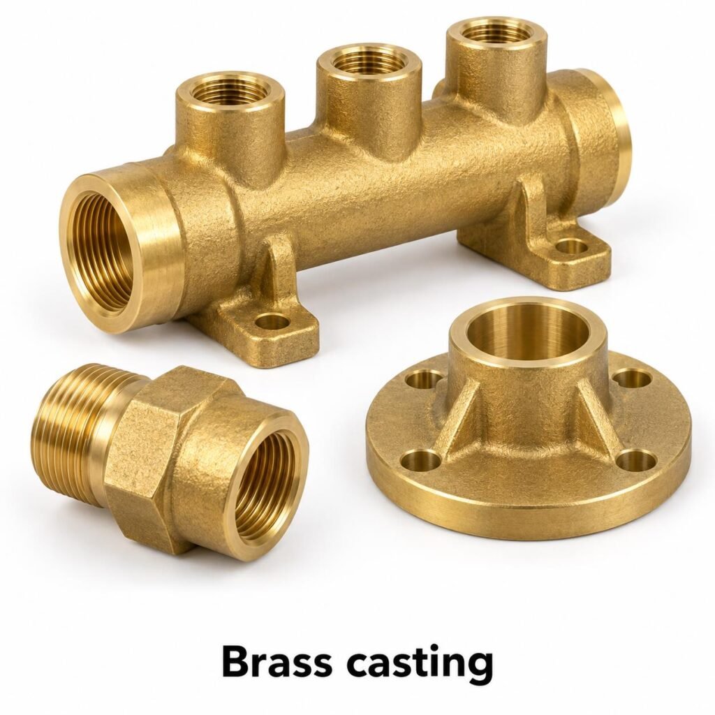
CC761S CuZn16Si4-C Brass Casting from Brass Parts India
CC761S CuZn16Si4-C is a high-copper silicon brass casting alloy, also described as silicon tombac. Its silicon addition makes it materially different from the leaded yellow brasses C85700 and C85400. It can be considered for engineered components requiring a combination of casting detail, strength and environmental performance, subject to the actual process and service conditions. It must not be described as automatically lead-free: the listed composition permits up to 0.8% lead.
Discuss silicon brass engineering components and complex cast housings with Brass Parts India. Send your drawing, required quantity and inspection requirements for a technical quotation.
Request a CC761S casting quotation
CC761S chemical composition
Reference composition in mass percent. Verify the agreed material standard and edition for production acceptance. Maximum values are limits, not required additions.
| Property or element | Reference value |
|---|---|
| Copper | 78–83 |
| Silicon | 3–5 |
| Zinc | remainder |
| Lead | 0.8 maximum |
| Aluminium | 0.1 maximum |
| Iron | 0.6 maximum |
| Manganese | 0.2 maximum |
| Nickel | 1 maximum |
| Phosphorus | 0.03 maximum |
| Tin | 0.3 maximum |
| Antimony | 0.05 maximum |
CC761S physical properties
Indicative reference information for material selection. Typical physical values are not component performance guarantees.
| Property or element | Reference value |
|---|---|
| Material family | silicon brass / silicon tombac |
| Indicative density | approximately 8.3 g/cm³ |
| Nominal silicon content | 4% (permitted range 3–5%) |
| Nominal zinc content | 16% (zinc is the remainder) |
| Electrical and thermal design values | request grade- and condition-specific verified data |
CC761S mechanical properties and casting condition
Published foundry references show tensile strengths around 400–500 MPa for several casting routes, with process-dependent elongation and hardness. One published supplier condition lists 530 MPa tensile strength, 370 MPa yield strength, 5% elongation and 150 HB. These supplier figures are not universal EN minima and should not be transferred to an unspecified process or section thickness.
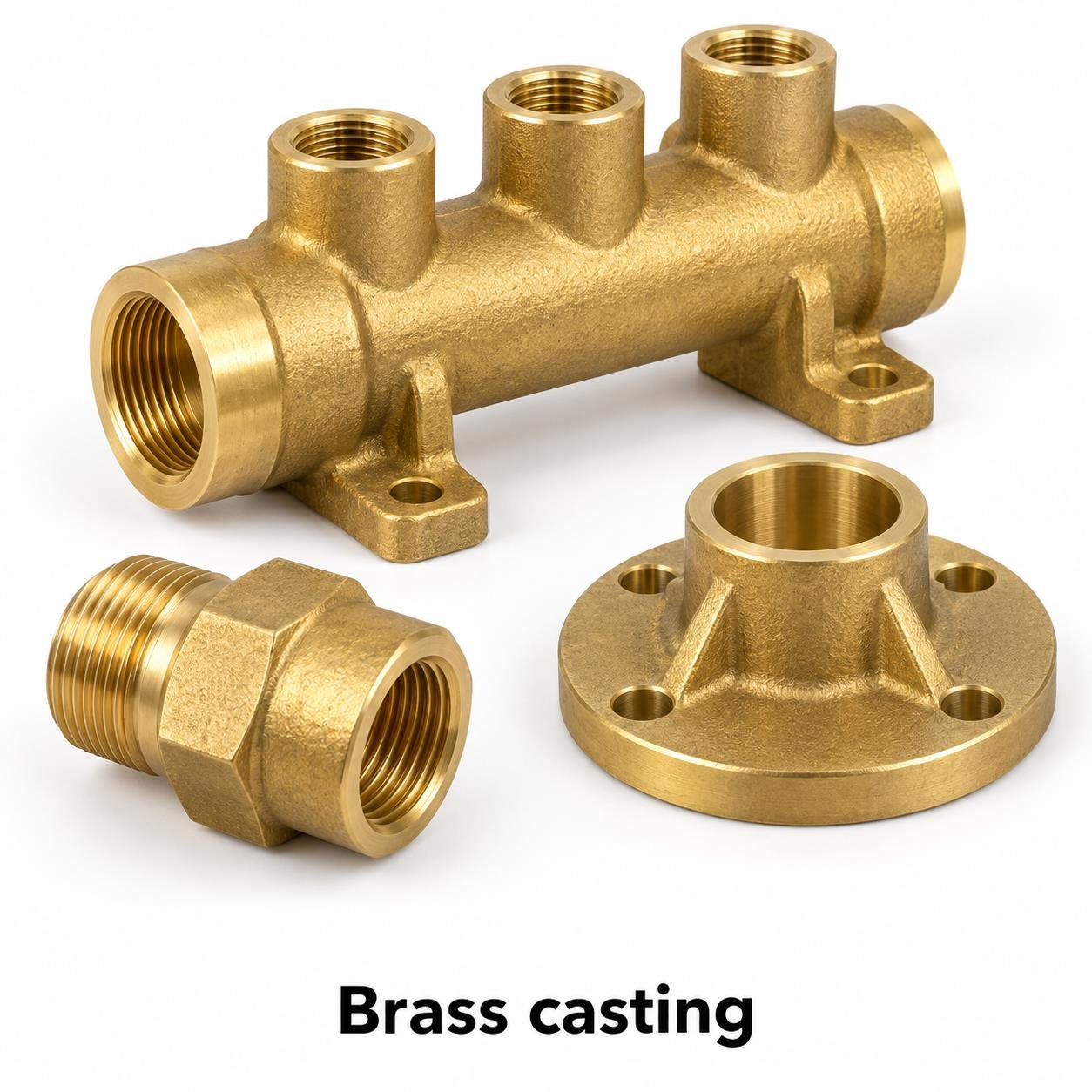
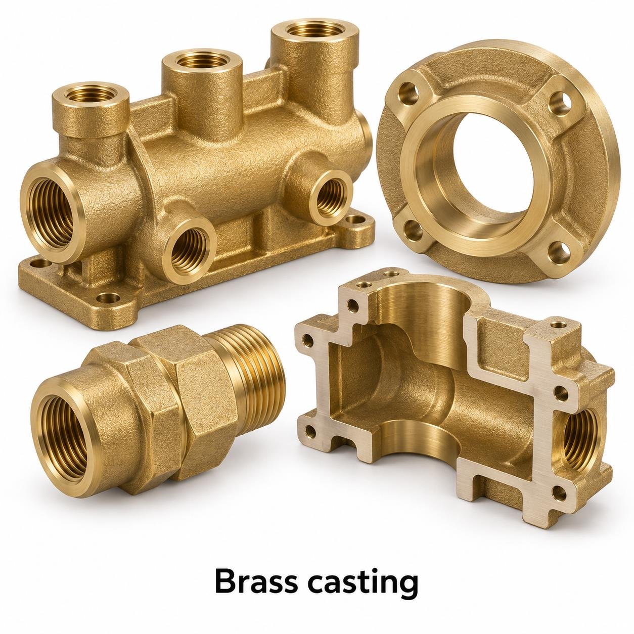
CC761S brass casting from Brass Parts India covers drawing-based cast brass components for electrical OEMs, EPC contractors, power utilities and industrial distributors. Typical enquiries include fitting bodies, valve housings, manifold blocks, connector bodies, flanged adaptors and mounting brackets. Selection connects alloy selection, repeatable geometry and machined sealing interfaces with the approved alloy, casting route and finished-part specification. Send the drawing, quantity and service requirements for a component-specific quotation.
Detailed product overview
Material identity and purchasing designation
CC761S brass casting produces copper-zinc alloy components by filling a prepared mold with a specified foundry alloy. Yellow brass, red brass and specialized low-lead grades have different compositions. A wrought machining brass designation is not a substitute for a casting grade without engineering approval. State the standard designation and required supply condition on both the enquiry and the purchase order. The description should remain consistent across the drawing, quotation, material certificate and inspection record. This avoids a technically different alloy being accepted because its commercial name sounds similar.
Threaded and sealed fitting bodies
Casting creates the outer envelope while machining establishes threads, seats and gasket faces. Specify locating datums, thread form, engagement length and gauging requirements. A nominal pipe size does not define the complete component. Allow sufficient wall stock around intersecting bores to accommodate core-position variation and final machining.
Plating and cosmetic finishing
Distinguish cosmetic areas from electrical contact and sealing faces. Coating thickness affects fit, so agree masking and post-finish dimensions. A uniform finish must not conceal unacceptable defects. Define whether repairs, impregnation or local dressing are permitted and what evidence should accompany a finished casting.
Drawing control and critical interfaces
A casting drawing should distinguish the as-cast envelope from the surfaces that will be machined. Mark datum pads, bore axes, bolt circles, sealing faces and minimum wall sections. Include draft and fillet expectations where they affect assembly clearance. The model explains shape, while the controlled drawing defines tolerances and acceptance. For fitting bodies, locating surfaces and access for cutting tools should be reviewed before tooling is released. Unspecified cosmetic features should not become hidden acceptance requirements after manufacture.
Production quantity and supply condition
Prototype quantities, maintenance spares and repeat production have different tooling economics. State the initial order quantity and expected annual usage so the proposed process can be assessed over the intended program. A cleaned casting, an oversize machining blank and a fully finished component are different deliverables. Define which operations are included and which remain with the purchaser. Where a legacy sample is supplied, agree how worn surfaces and missing drawing information will be interpreted before a replacement geometry is approved.
Key features and engineering requirements
- Drawing-defined cast brass castings with an identified alloy specification.
- Process selection matched to geometry, cores, section thickness and order quantity.
- Defined machining stock for bores, threads, mounting faces and sealing interfaces.
- Inspection requirements linked to component function and critical zones.
- Material identification and documentation specified with the purchase order.
- Supply condition, surface finish and packing agreed before production.
Machining allowance and datum strategy
Machining stock must cover casting variation without adding unnecessary weight or cutting time. Define allowances by surface rather than applying one blanket value to the whole component. A bore and an external flange may need different allowances. Establish how the first machining operation locates the casting, then how subsequent operations preserve the datum relationship. For cored components, check minimum wall thickness after machining. Stock allowance is a process-design decision and should be agreed before the pattern or permanent tool is finalized.
Surface condition and defect acceptance
As-cast texture, gate-removal marks and parting lines differ from machined surface roughness. Identify visible areas, functional areas and surfaces that will be covered during assembly. Specify acceptable dressing and whether weld repair, impregnation or other corrective work is allowed. Inspection should distinguish harmless surface texture from defects affecting strength, leakage or fit. A reference sample can support an appearance requirement, but it should supplement measurable criteria and a documented agreement about critical surfaces and permissible repair.
Threads, fits and mating components
The finished component must fit the mating assembly, not merely match its own isolated dimensions. Specify thread standard, pitch, tolerance class and usable engagement length. State fit requirements for shafts, bushes and locating pins. Where a coating is applied, clarify whether dimensions are measured before or after finishing. Chamfers and edge breaks should support safe assembly without reducing sealing land or contact area. Provide the mating-part information needed to review tool access, assembly sequence and inspection-gauge selection.
Heat treatment and property verification
Heat treatment is grade-dependent and should be specified only where it is required by the alloy standard or component design. Define the delivery condition and associated testing rather than requesting a generic treatment for all copper alloys. A separately cast test coupon may not represent every local section of a complex component. Agree the sampling arrangement and any supplementary verification. Hardness, tensile properties, conductivity and metallography answer different questions and should be selected according to the function of the supplied casting.
Identification, traceability and packing
Specify part number, drawing revision and lot or heat identification where traceability is required. Marking location and method should avoid sealing faces, thin walls and electrical contact areas. Keep documentation linked to the shipment and to the relevant inspection records. Packing must prevent impact damage to edges, threads and machined surfaces during handling. Separate finished faces where components could rub against each other. For distributors, agree unit labels and batch segregation so repacking does not break the connection between material identity and supplied parts.
Technical specifications
| Parameter | Purchasing requirement |
|---|---|
| Product category | Metal casting |
| Material family | cast brass |
| Typical components | fitting bodies, valve housings, manifold blocks, connector bodies, flanged adaptors and mounting brackets |
| Production route | Drawing and alloy dependent; confirmed in quotation |
| Supply condition | Cleaned casting, rough-machined blank or finished component as ordered |
| Dimensions and weight | According to approved drawing; capability reviewed before acceptance |
| Casting tolerances | Agree relevant ISO 8062 tolerance and machining-allowance requirements |
| Machined tolerances | Feature-specific; no universal tolerance claimed |
| Surface finish | As-cast texture and machined roughness specified separately |
| Testing | Material, dimensional and functional checks according to the agreed inspection plan |
| Documentation | Specify certificate type, traceability and reports before order release |
Product types and variants
| Variant | Typical procurement purpose | Drawing detail to define |
|---|---|---|
| As-cast component | Near-net blank for subsequent operations | Draft, fillets, gate dressing and casting tolerances |
| Rough-machined blank | Stock prepared for customer finishing | Reference datums and remaining allowance |
| Finish-machined component | Ready for inspection against finished drawing | Fits, threads, sealing faces and edge condition |
| Cored housing or body | Internal passage or hollow geometry | Core position and minimum final wall thickness |
| Ring, sleeve or bush | Rotational component considered for centrifugal casting | Bore stock, length, concentricity and material condition |
Applications in industry
Application selection for cast brass should begin with alloy selection, repeatable geometry and machined sealing interfaces. The component examples describe enquiry categories rather than a guaranteed rating or blanket suitability. The equipment designer remains responsible for the complete assembly, including loads, temperature, fluid compatibility and installation conditions.
| Customer group | Component or project context | Information needed |
|---|---|---|
| Electrical OEMs | Drawing-specific equipment bodies, supports or connection components | Electrical function, joint requirements and any conductivity requirement |
| EPC contractors | Plant equipment, pump and valve packages, maintenance spares | Project specification, service medium and inspection hold points |
| Power utilities | Auxiliary equipment, cooling systems and specified connection hardware | Duty conditions, traceability and equipment approval requirements |
| Industrial distributors | Repeat supply of identified casting components | Part number, drawing revision, alloy and stocking quantity |
Manufacturing process and casting methods
The production route is chosen after reviewing the material, geometry and order. The methods below are alternatives to assess; their inclusion does not mean every method is appropriate or available for every grade and part.
| Method | Suitable geometry or purpose | Important limitation |
|---|---|---|
| Sand casting | Complex housings, larger sections and flexible tooling | Surface texture, cores and allowances require review |
| Green sand casting | Repeat mold production using a moisture-containing sand system | Mold properties and gas control affect casting quality |
| Shell molding (resin sand) | Detailed smaller components using resin-coated sand shells | Tooling cost, core design and thermal behaviour must be assessed |
| Resin-bonded sand casting | Complex molds or cores with a chemically bonded sand system | Binder selection, gas evolution and reclamation differ from shell molding |
| Centrifugal casting | Rings, sleeves and rotationally symmetric blanks | Bore cleanup and machining allowance are required; not for arbitrary housings |
| Permanent mold casting | Repeat components where alloy and geometry suit reusable molds | Tooling, thermal control and core limitations require confirmation |
From drawing review to casting
The planned sequence begins with drawing review, alloy confirmation and process selection. Pattern or tool design establishes the parting arrangement, cores, draft and machining stock. Melt preparation and handling must preserve the required composition. Gating and feeding are planned around section changes and solidification behaviour. After pouring and cooling, the casting is removed from its mold, gates and risers are cut away, and the surface is cleaned. Each stage should support the agreed final acceptance criteria.
Secondary operations and release
Following cleaning, any specified treatment is completed in the agreed sequence. Rough machining can establish reference surfaces before critical features are finished. Inspection then checks dimensions, material identity and the functional tests required by the order. The supplier and purchaser should agree first-article approval before repeat production where the program requires it. Final release connects the accepted part to its documentation, marking and packaging. Changes to material, tooling, process or drawing revision should be reviewed before subsequent deliveries.
Quality standards and certification requirements
Specify the applicable standard and its edition in the purchase order. ASTM B584 addresses copper-alloy sand castings for general applications; ASTM B148 addresses aluminum-bronze sand castings; ASTM B271/B271M concerns copper-base centrifugal castings. EN 1982 provides a European framework for copper and copper-alloy ingots and castings. The selected standard must cover the actual alloy and product form.
Where requested, define the material inspection document, including any EN 10204 requirement, together with sampling and traceability. Dimensional inspection, chemical analysis, pressure testing and nondestructive examination are separate requirements. Request applicable current quality-system certificates and their scope during supplier qualification. This page does not claim that every casting is certified to every named standard, nor does a quality-system certificate replace product-specific acceptance evidence.
Why choose Brass Parts India
Use Brass Parts India as the enquiry point for a defined casting component rather than an unspecified metal shape. A useful technical quotation connects the alloy, drawing revision, production route, supply condition and inspection requirements. This makes it easier for purchasing and engineering teams to compare proposals on the same basis and identify exclusions before an order is placed.
For repeat supply, retain the approved first article, material specification and inspection plan as the purchasing reference. Discuss proposed substitutions or process changes before release. Request evidence for any capability, certification or special test that is essential to your project. Clear requirements and documented acceptance provide a more reliable basis for supplier selection than an unsupported general performance claim.
Frequently Asked Questions – CC761S brass casting
What is CC761S brass casting?
CC761S brass casting is an engineered metal casting used in industrial machinery, valves, pumps and OEM assemblies. Final suitability depends on the approved specification and application conditions.
Where is CC761S brass casting commonly used?
Typical applications include industrial machinery, valves, pumps and OEM assemblies. Confirm load, environment, mating parts and applicable standards before selection.
Which materials are available for CC761S brass casting?
Specify the grade identified at the top of this page. State the exact grade because similar commercial alloys can differ in composition and performance.
Which sizes can be supplied for CC761S brass casting?
Standard and custom sizes can be reviewed from casting drawing, machining allowance, wall section and critical dimensions. Nominal size alone may not define compatibility.
What dimensions are required to order CC761S brass casting?
Provide casting drawing, machining allowance, wall section and critical dimensions, with units, tolerances and drawing revision.
Can CC761S brass casting be made to a custom drawing?
Yes. Custom geometry, threads, tolerances and features can be assessed from a dimensioned drawing or approved sample.
Which thread standards are available for CC761S brass casting?
Relevant Metric, BSP, BSPT, NPT, NPTF, PG, BA or BSW threads may be considered. Specify form, size, pitch, class and engagement length.
Which finishes are offered for CC761S brass casting?
Options may include as-cast, machined, polished or coated. Specify coating type, thickness, appearance and corrosion or conductivity needs.
What tolerances can be maintained on CC761S brass casting?
Tolerance depends on material, size, geometry and process. Mark critical dimensions and fits clearly on the drawing.
How should CC761S brass casting be installed?
Check mating dimensions, orientation, sealing or retention method and specified tightening torque before use.
How is CC761S brass casting inspected?
Inspection can cover material identity, critical dimensions, threads, finish and drawing-specific functional checks.
Which quality documents are available for CC761S brass casting?
Material certificates, dimensional reports and coating or test records can be agreed at quotation stage.
Are samples available for CC761S brass casting?
Prototype or pre-production samples can be reviewed for new custom parts, subject to tooling and material requirements.
What are the MOQ and lead time for CC761S brass casting?
Minimum quantity and lead time vary with material, size, tooling, finish, inspection and order volume.
What is needed for a CC761S brass casting quotation?
Provide the drawing or specification, material, dimensions, tolerances, finish, quantity, inspection, packing and destination.
How to use the chemical composition table
The composition table expresses mass percentages. A range specifies a lower and upper boundary, while a maximum limits an element without requiring its deliberate addition. Zinc described as remainder is calculated from the complete alloy composition rather than assumed to be a fixed percentage. The nominal chemical designation is a convenient material name, not a substitute for the analytical limits. Request a heat analysis identifying the supplied material and compare every specified element with the purchase specification. Where copper includes nickel, retain that qualification when comparing a certificate. An analysis that checks only copper and zinc can overlook an important difference in lead, silicon, aluminium or residual elements.
Physical properties and practical design calculations
Physical data help estimate mass, heat flow and electrical behaviour, but they do not establish a finished component rating. Density multiplied by net solid volume gives a preliminary finished-part mass; cavities, threads and machining stock must be treated separately. Thermal conductivity affects the temperature gradient through a component, while expansion influences fits during heating and cooling. Electrical conductivity of the alloy is only one contributor to resistance in an assembly: contact area, joint pressure, surface films and coatings also matter. Use temperature-appropriate values for a design calculation and identify the source and condition of every input. Where a verified value is unavailable, request it rather than borrowing a number from another brass grade.
Understanding tensile, proof and hardness results
Tensile strength measures the maximum engineering stress in a specified tensile test. Proof strength or a yield value indicates a different point on the stress-strain response, and the method used to determine it must be stated. A 0.2% proof value is not interchangeable with a yield value measured at 0.5% extension. Elongation depends on the test specimen and gauge length as well as the material condition. Hardness provides useful information about local resistance to indentation but does not prove that all tensile requirements are met. Agree whether samples are separately cast, attached to the component or removed from a specified location. Retain the test method, specimen identification and result together.
Selecting a casting route for the component
Begin process selection with the component geometry and required production volume. A cored housing, a simple ring and a thin decorative cover present different moulding and feeding problems. Sand moulding can accommodate complex internal features, while a reusable metal mould may justify its tooling cost for a suitable repeat component. A particular alloy being used in pressure die casting elsewhere does not establish that this route is suitable or available for a specific order. Compare proposed routes using finished-part cost, tool life, machining stock, rejection risk and inspection needs. The quotation should identify the offered process clearly so that property expectations and dimensional allowances match the manufacturing route.
Pattern design, draft and parting lines
A casting pattern needs features that help the mould release and remain intact. Draft should be coordinated with the direction of withdrawal and the surfaces that will later be machined. The parting line affects mismatch, flash removal and the appearance of an exposed surface. Locating the parting plane through a functional sealing feature can create avoidable finishing work. Discuss critical surfaces before finalising tooling, and distinguish the casting drawing from the finished drawing. A pattern dimension may include allowances that are deliberately absent from the final component. Tooling approval should record the agreed parting arrangement, gate locations, core prints, identification marks and remaining stock on machined faces.
Wall transitions and solidification planning
Abrupt changes from a thin wall to a heavy boss can create local hot spots and feeding difficulties. A gradual transition, suitable radius and balanced section design can make the component easier to cast consistently. Adding metal everywhere is not necessarily an improvement: excess mass may increase local shrinkage risk and extend machining time. Review the location of thick junctions, isolated pads and blind pockets with the foundry. Functional requirements such as bolt bearing area or minimum pressure wall thickness still govern the design. Any proposed change to those features must be approved by the design owner. The aim is a casting geometry that supports both service performance and repeatable solidification.
Cores and internal passages
Internal passages require attention to core positioning, support, cleaning and inspection access. Core movement can alter the minimum wall even when the outside dimensions appear acceptable. State the minimum finished wall in critical regions and identify how it will be checked. Intersecting passages should be designed so that residual sand, chips and cleaning media can be removed. A passage that cannot be inspected visually may require a suitable alternative verification method. Before tooling release, review whether a passage should be cast, drilled or formed through a combination of both operations. This decision influences tool cost, cycle time, material yield and the risk of leakage after machining.
CNC turning and milling of brass castings
Machining converts selected cast surfaces into controlled interfaces for assembly. Turning can establish bores, spigots, shoulders and threaded features, while milling can create mounting faces, slots and accurately located holes. The fixture should locate from stable datums without distorting a thin or irregular casting. A casting may require an initial operation to establish those datums before final machining begins. Describe critical relationships such as concentricity, position and perpendicularity rather than relying only on individual linear dimensions. The proposed machining sequence should leave enough material to clean up the surface while avoiding unnecessary stock removal. Request a drawing review where tool access or clamping space is restricted.
Machining allowance and surface cleanup
Machining stock must cover the expected variation in the casting and provide a sound finished surface. Too little stock can leave an unmachined patch or expose an off-centre bore; too much increases weight, tool time and material loss. Allowances can differ between faces according to orientation, casting size and process. Identify whether a dimension applies to the raw casting, the rough-machined blank or the finished part. For a supplied blank, specify the remaining stock and the reference surfaces the customer will use. When first articles are inspected, compare actual cleanup with the proposed allowance so that any tooling correction is made before a larger production batch.
Threaded connections and sealing details
A threaded port needs more information than a nominal diameter. Specify the thread family, pitch, tolerance class, engagement length and any required gauge acceptance. A parallel thread with a face seal behaves differently from a tapered pipe thread that seals through the threaded joint. Define the sealing face, counterbore or gasket seat separately, including finish and edge condition. Deburr intersections without damaging the first full thread or reducing the sealing land. If coating is required, state whether gauging takes place before or after finishing. Where the casting will connect to an existing assembly, provide mating-part information to prevent an apparently correct thread from producing an unsuitable joint.
Leak testing and pressure-containing parts
A material grade does not assign a safe working pressure to an arbitrary housing. Pressure capability depends on wall thickness, geometry, defects, temperature, joint design and the governing equipment requirements. For pressure-containing components, agree the test medium, pressure, duration, fixture arrangement and acceptance criteria before production. Identify whether every part is tested or whether a defined sampling plan applies. Test records should connect the result to the batch or individual part as required. A successful room-temperature leak test is not evidence of fatigue life, high-temperature strength or compatibility with every service fluid. Those requirements need separate engineering assessment and, where appropriate, additional qualification.
Surface finish, polishing and coatings
Specify as-cast appearance separately from machined roughness. A cast surface may retain a controlled texture, whereas a sealing face may require a measurable roughness and a defined lay direction. Polishing changes appearance and can remove small amounts of material from edges and lettering. Coatings introduce further requirements for adhesion, thickness, coverage, colour and dimensional allowance. Mask electrical contacts, sealing faces or threaded features when the specification requires it. An approved appearance sample is useful for cosmetic features, but it should accompany clear acceptance criteria. Review the complete sequence of cleaning, polishing, coating and final inspection so that a finishing operation does not compromise a previously accepted feature.
Corrosion and service-environment review
The service environment is central to alloy selection. Fluid chemistry, temperature, flow, deposits and contact with other metals can influence corrosion behaviour. A brass that performs adequately in one indoor application may need a different assessment in a wet, saline or chemically aggressive location. Discuss dezincification and stress-corrosion concerns where they are relevant to the actual service conditions. Avoid treating a bright plated surface as proof of long-term corrosion resistance. For a critical application, identify the expected exposure, maintenance regime and applicable test requirements. The material designation, manufacturing condition and finished surface should be reviewed together rather than selected independently from a generic list of alloy advantages.
Lead content and application restrictions
Several grades in this product family contain deliberate lead additions, while a silicon-containing grade can still permit residual lead. Neither colour nor a commercial name establishes compliance with a lead limit. If a component is intended for drinking-water contact, food equipment, an electrical product or another controlled application, provide the exact material and product requirements for review. A chemical certificate and an end-product approval answer different questions. Do not assume that a certificate for one design or destination covers every variation. Where an alternative alloy is needed, obtain engineering approval and review the resulting effects on machining, casting behaviour, mechanical properties and the finished component cost.
First-article inspection and approval
A first article should demonstrate that the proposed production route can deliver the drawing requirements. Number the drawing characteristics and link them to measured results in the inspection report. Include material identification, critical dimensions, threads, surface condition and any specified functional tests. Record the tooling version and process condition so that the approved sample has a meaningful connection to repeat supply. A customer may accept a documented deviation for a sample without accepting it for production; keep those decisions explicit. Once the first article is approved, use the agreed drawing and inspection plan as the reference for subsequent orders rather than relying on an informal comparison with a loose sample.
Batch traceability and material certification
Traceability begins before machining and should remain intact as castings move through cleaning, inspection and packing. Agree whether identification is required by heat, production lot or individual component. Marking must be placed where it will remain legible without damaging a functional surface. If parts are too small to mark, labelled containers and controlled batch segregation may be appropriate. State the required inspection document at quotation stage, including any specific EN 10204 designation. A certificate should describe the actual supplied material and agreed tests. Retain a clear connection between the purchase order, drawing revision, material analysis, inspection records and delivered quantity so that later enquiries can be resolved efficiently.
Dimensional inspection and measurement planning
Measurement should follow the drawing datums and the function of the component. A coordinate measurement report is useful only if the setup, probing strategy and reference system match the specified requirements. Thread gauges, bore gauges, surface instruments and dedicated fixtures can be more suitable for particular features. Consider access to internal dimensions before the design is frozen. For very tight requirements, account for measurement uncertainty and the temperature at which the part is checked. Agree which characteristics require full inspection and which use an accepted sampling plan. A clear inspection strategy helps avoid a disagreement in which the supplier and customer measure the same feature in different ways.
Cleaning, deburring and shipment preparation
Cast and machined components should be delivered in a condition appropriate to their intended assembly process. Identify unacceptable residues such as loose sand, machining chips, burrs, oil or polishing compound. Blind cavities and intersecting holes deserve particular attention because contamination may remain hidden after external cleaning. Define any quantitative cleanliness requirement rather than simply requesting a clean part. Protect finished threads and sealing faces during handling and shipment, and separate surfaces that could rub together. Packing should preserve batch identity and prevent damage from movement inside the carton or crate. Discuss humidity protection, storage duration and the removal of temporary protective materials before the component is installed.
Cost drivers and quotation comparison
Compare quotations on the same finished-part basis. Raw metal cost is only one contributor: tooling, casting yield, machining time, finishing, testing, documentation and packing can materially affect the delivered price. A heavier casting may have a lower price per kilogram but a higher cost per usable component. Clarify whether the quotation covers an as-cast blank or a fully inspected machined part. State the expected annual demand and order batch size because they influence tooling and setup economics. Ask how proposed design changes affect total cost and acceptance risk. A useful commercial comparison includes the agreed exclusions, delivery terms and validity period alongside the quoted unit price.
From enquiry to repeat supply
Begin an enquiry with a controlled drawing, material designation and realistic quantity forecast. Add the service conditions and inspection requirements that are essential to the application. The technical review should resolve questions about process selection, machining stock, tolerances, finishing and testing before tooling is released. Once samples are available, record the inspection results and customer approval status. Repeat orders should identify the same approved drawing revision, or clearly communicate a change. Discuss any proposed change to alloy, tooling, manufacturing route or outside processing before production proceeds. This sequence creates a shared technical basis for quotation, sampling and supply, and reduces avoidable uncertainty when the order reaches final inspection.
Information to include with your request for quotation
Please include the component name, drawing number, revision, units, annual quantity and expected batch size. Specify the alloy and standard edition, whether a casting or finished machined component is required, and any customer-controlled material restrictions. Mark critical dimensions, sealing surfaces, threads and appearance areas. Provide the working environment, operating temperature and required tests when these influence selection. State your documentation, marking, packing and delivery requirements. If an existing sample is supplied, identify whether it is an approved reference or merely a starting point for development. Clear enquiry information lets Brass Parts India review the actual component and respond with a defined scope rather than a generic material-only quotation.
Request a drawing review for CC761S
Contact Brass Parts India with your drawing and annual demand to discuss silicon brass engineering components and complex cast housings. Specify the material, process, machining, finish and test requirements so that the quotation covers the complete component.
Send your casting enquiry | Return to Brass casting
Explore brass casting grades
C85700 Leaded Yellow Brass Casting
C85400 Leaded Yellow Brass Casting – CDA 854 Commercial Yellow Brass Casting
CC750S CuZn33Pb2-C Brass Casting
CC754S CuZn39Pb1Al-C Brass Casting
CC761S CuZn16Si4-C Brass Casting